Sunday, May 29, 2011

More on the FS/BS

I was reading another blog posting the other day that read " Its been a month since my last post" and I thought to myself what a slacker. As I read through his posting I noticed on his favorite blog list 'Ian Phemisters Muswellbrook Blog' 1 Month ago!  Gee now whose the slacker now! Well I have been pretty busy rebuilding my old garage. Just about finished the house stuff and soon to start on the railway room. Thought I better get in and post something up and make up for lost time.

I love the excitement and anticipation of waiting for new models to turn up in the post. A week or so ago I received my long awaited FS/BS coaches. These are very nice cars out of the box but still needed work to bring them up to scratch for both Muswellbrook and for running on our Exhibition Layout. As usual I have left this job to the last minute as I want to take these to the Toowoomba Exhibition to run on the layout next weekend. I also had a few locos to finish off (decoder installs and weathering) along with a trial weathering of LCH's. Below is what I did to my Coaches.

Bogie's
There was a discussion on Ray Pilgrim's Bylong Blog regarding the small springs for the power pickup for the lighting. Some of the cars had crushed springs. These can be replaced with KD coupler springs. All of mine were OK. I did find however that they did not roll freely. Investigation found that all the brake shoe details were rubbing on the wheel treads. No matter how many times I unwound the brake spider they would not loosen off! I gently removed the brake shoe casting from the bogie and proceeded to cut the brake arm just behind the brake shoe, then removed a millimeter from each end of the arms. I then glued the two halves back together using styrene angle for bracing. Make sure that the angle goes to the inside of the arm once back in the bogie. Once the glue had completely dried I reinserted them back into the bogie. To further aid in the free running of the car I applied a small amount of graphite powder to the axle boxes. They were then reinstalled back onto the car. aaaarrrrr much better! 6 cars still not good enough for one Austrains 36!


Body details.
I had consulted the Aus railway gooroo James McInerney regarding the colour of the interiors for these period cars (more on this later). He also mentioned that the lamp brackets were in the lower position. Not prototypical for these earlier colour schemes. Reference from the coaching stock book shows the brackets just above the top buff lining. The lamp brackets are etched brass and can easily be removed with long nose pliers. New holes were drilled and the brackets inserted into the new holes. I filled the old holes with Tamiya putty and touched up the grey putty with Indian Red paint. Once weathered the repair can hardly be seen. I also noticed in the photos that the end hand rails are on the end of the car rather than the side like the model. This seemed a fair bit of work so I agreed to be happy with how they are.


Interior
The gaudy interior plastic colour looks terrible. The body is very easily removed by gently pulling the chassis down away from the body. I then removed the two screws holding the light board in, then a further three screws for the seating . I also removed the weight strips, light switch with light board attached and set aside. This now allows me to paint and weather the chassis and bogie's. With the seating section in hand I carefully removed the two wall sections from the sides of each of the compartments. Now we can paint the seats.
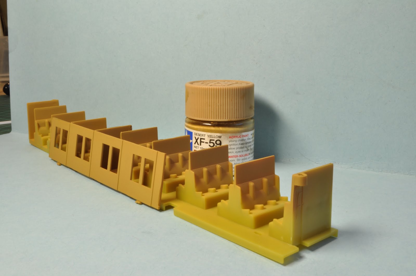
James explained that the interior of the BS First class coaches had light coloured varnished timber walls with dark green seat cushions, while the FS Second class cars had varnished walls with maroon seats. I chose a colour close enough for the walls, Tamiya Desert Yellow XF-59. I air brushed the panels above the seats and all the centre wall sections with the desert yellow along with the removed walls. Once dried I made up universal masks from large heat shrink for the panels above the seats. All the green seats were painted, Tamiya J.A. Green XF-13. Then all the maroon seats. For the maroon I mixed both Tamiya red X-7 and Flat Blue XF-9. All the compartment sides can now be re glued back to the seat casting.
I found a photo that showed some of the blinds lowered over the windows. Now is a great time to do this. I started by painting a sheet of printing paper randomly with Model Master Sand and Floquil Earth mixing the two together to create an uneven colour. Both these were slightly thinned with general purpose thinners. Once dried I cut off 8mm wide strips, then cut these into 10mm long squares. The window sections can be removed by carefully running a scalpel blade between the body and the widow plastic. The small squares were then glued with PVA at the top of each window randomly selecting some that were to be lowered. Some half way, some all the way, some a quarter way down......or up!. I even glued blinds on for the ones right up leaving a small section visible at the top of the window to show the blind is there. Once the glue had completely dried I trimmed off the excess with a sharp scalpel. These are now ready to be installed back into the car.


Weathering.
While the widows are out, it is a great time to weather the car. I gave the entire body a light wash with my black Oil colour and Micro sol mix. While these were drying, I gave the bogie's and wheels a hit with black etch. I covered the pickup springs with short pieces of heat shrink to protect them from paint. All the chassis sides and bogie's are then lightly air brushed with Floquil Rust. While this is still soft I quickly moved around the rust colour with a turps wet paintbrush and allowed it to dry. It is a great affect for light rust. All the bogie's and underframe's are then lightly misted with weathered black to tie it all together.
When the wash on the body sections are dry I sealed them so that they can be handled. I temporarily married up the bodies with chassis and lightly misted the lower sections of the cars with Floquil grime to simulate dust. The roofs were also given a spray with weathered black and a bit of Engine Black for weathering. I did want to simulate the malthoid roof sections but am still unsure how to do this without removing the roof vents......Any ideas? Again the cars are given a coat of flat finish to seal it off.
The window glass can now be put back into the car along with reassembling all the interior bits onto the chassis. I have ordered 250 seated people from china that will be perfect, however they have not turned up yet. They will have to run empty at Toowoomba.

Finishing off. 
Now that all the cars are back together (that didn't take long) I touched up a few details. I splashed about a bit of gloss black wet with isopropil to simulate oil from the axle boxes. White for the brake spiders and release levers and a bit of gold for the door knobs. I will have a go at lining the doors at some stage when I get brave. The end result looks great. I'm sure the 100 odd passenger will agree.


I mentioned earlier that I done a trial on weathering a couple Eureka LCH's. Muswellbrook will need a heap of these. I was shown this technique by Dean Bradley at the New England convention. He used Derwent tinted charcoal pencils to weather a timber body louver van. I started by applying the same weathering to the chassis section (I removed the coal bunker) in the same way as the FS/BS cars above. The coal bunker was then lightly sprayed with Floquil Concrete as a base colour. Not heavy enough to cover the lettering. I brushed the metal brace details and bits with Floquil Rust. The bunker was then 'coloured in' with the Peat TC18 charcoal pencil. This was then brushed in with a stiff brush. I added in the same way a couple other colours for variation, Natural TC20 and Burnt Earth TC19. I then used a small amount of black pastel powders for a bit of extra colour. Both cars then sealed with flat finish. Next time I might 'Rust Up' the chassis a bit more but overall I am happy with the result.


That's all for now.

Ian
 

Tuesday, April 12, 2011

Well Wagons.......Going....Going.....GONE!

Hi All,
Just a bit of an update. After just two days of the well wagon being officially on the market, We have SOLD OUT. All fifty are gone. We just could not believe it. We have already put in place the ordering process for a second set of components for the 2nd run of the Well wagon. Those who missed out, don't worry we will have more stock shortly. You can email us and set one aside so you don't miss out. Again if you did not recieve the email update and are wanting to be added to the list, email me so I can add you in. mailto:andian.models@gmail.com%20.
Those who were lucky enough to get one this time around, you will see them shortly. Hope you enjoy the challenge of putting one together.
We will keep you posted.


Cheers
Ian

Sunday, April 10, 2011

AndIan Models LWW Release

Hi all,
Today Andrew Lee and myself put together all the components for our first kit, The NSWGR LWW Well wagon.
According to John Beckhaus’s Railway Freight Wagons book, these wagons were built by Ritchie Brothers and the Railway Workshops between 1909 and 1912. Two survive in the collection of the Dorrigo Steam Railway and Museum, and are currently located at Ulong. These wagons were measured and photographed for the purpose of building this model. Like most wagons of this era, a number of modifications have taken place over the life of the wagon. The obvious visual differences are that the wagon originally had hook drawgear, Buffers and spoked wheels. By the end of its service life , and currently in preservation, the buffers have been removed, Auto couplers replace the hook drawgear, and the wheels have been changed to disk wheels. The kit represents the later condition, but it should be fairly easy to backdate the model if required. There were only three of these wagons built.

For those who are new to this blog and have not read my older AndIan Models post, Our LWW kit is constructed of etched brass. The kit comes with all components to complete the kit including Ian Lindsay Models Archbar Bogies with RP25-88 wheels, scale KD whisker couplers, brass wire, decals, instructions etc. These kits are intended for those with some experience of assembling this type of kit. There are a number of steps that are quite fiddly, and will seem to be a bit daunting to a newcomer to this type of construction. The best advise is to ask for help - if you belong to a model railway club, there is bound to be a member who can assist you. Doing the job yourself, with the appropriate advise and assistance, is the best way to acquire new skills, and create confidence to go tackle other projects of the same or greater difficulty.


At this stage the kits can only be purchased direct from AndIan Models by sending your details with your required quantity to PO Box 104, Bellingen, NSW 2454. Payment can be made by cheque, money order or by direct deposit (details emailed upon request). You best email me first if you want one!
andian.models@gmail.com

Alternatively you can purchase them from our EBay store http://cgi.ebay.com.au/ws/eBayISAPI.dll?ViewItem&item=180651916884&ssPageName=STRK:MESELX:IT . This allows payment from a credit card using PayPal.


The kits are $80 each including regular postage to anywhere in Australia. We have only 50 of these kits available. A second run may be done depending on demand and after the first run has been exhausted.
I have again added a couple photos of the pilot model and contents of the kit.
We have also started and email address list for updates on our future models. If you wish to be added to the list or for technical reasons you did not receive the latest email, email your details to andian.models@gmail.com


Photo taken from Ron Prestons 'Day Of The Goods Train' book.


That's all for now.

Cheers

Ian

Monday, March 14, 2011

Lines.......No Tigers!

This week I was asked to paint a couple of old Lima 38's for a friend. They had been modified quite some time ago with detailing components that were once available, not sure where from. He wanted them cleaned up a little so they could be put on EBay. He simply wanted them all over black with addition of brass numbers to make them resemble something along the lines of a 38. Painting them black was easy. A little hit with the Wattyl automotive etch black with the air brush made them look heaps better.
Looking at them being plain and boring on the workbench got the better of me so I dragged out some old lining pens that I acquired from a deceased estate. I have a few of these now but have not been game enough to give it a go........They are the ones with the little reservoir and small tube. I had some old Humbrol red enamel lying around and proceeded to try a bit out on a scrap piece of styrene. I glued a strip of thin foam packaging glued to the back of a 15cm steel ruler.

I also made a curve template to the same curvature of the valence of the 38 so as I could end up with nice even curved lines. The same was done for the tender corners as well. I done all the corners and curves first. Some of these needed to be allowed to dry before the next nearest curve could be done as the template sat atop the wet painted lines. Once all the corners and curves were allowed to dry I joined all them up with the straight lines with the steel rule. I only done one of the two 38's. The other was a streamlined version......I chickened out with this one as I did not want to tackle the whiskers.
Definitely not a Ted Flowers job, But certainly passable. The old 38 sold for $330 on EBay. The unlined one sold for about $220.

Another project I have started,  for another friend, is to paint two Classic Brass 32's. The job also entails fitting Tsunami sound decoders to both locos. The two were both completely stripped and soaked in thinners to remove all traces of clear coat. All parts were then treated to a dip in the caustic soda to remove all traces of oil etc. They were then given a coat of paint (everywhere) with my etch black.
The Tsunami decoders give the ability to add some great lighting affects to our models. Wanting something a little different I thought I would try and include a firebox light both under the loco and inside the firebox along with working marker lights, headlight and cab light. The classic 32 has a removable back head casting that has a hole in the casting for the fire hole door. There is also room for mounting a LED and resistor behind the door. I made up several light boards using PCB ties from Clover House. I ran a razor saw down the middle of a short piece and also across one of the two tracks. The Surface mount LED can be carefully soldered to the end of the board and 1K surface mount resister on either side of the cut in the track. The LED came with leads attached. Before removing the leads I determined the polarity of the LED before removing the wires and mounting to the board.I also added a little Tamiya Clear red so give a little extra orange glow.


One of these will be mounted under the loco between the back set of driving wheels. The other I mounted on the back of the back head using double sided tape so as the LED will shine through the fire hole.


For the cab light I decided to use an incandescent globe. These cab lights were not real good at the best of times and I did not want to really 'light up' the cab, just add a little extra glow. A trial and error test was done using different size resistors. This resistor for the cab light was mounted on the side of the back head casting under the drivers seat. You can see the cab light sticking up above the back head.
 For the front marker lights, I drilled out using a 1mm drill all the front markers for both locos before they were painted. I purchased from DCC Concepts some of their nano LED's. They say you can fit two of these in a 1mm hole. I have not yet fitted these but will see how they go. They are incredibly small.
 I was not going to add rear markers to the tender........But will see how the rest turns out. I might be over it all by then! 
Both the cab light and front markers will be wired to the function 5 output of the decoder and will I function map this to operate using function 1. (do away with the bell). The fire box lighting will be wired to the function 6 output and programmed with fire box flicker and mapped to button 4. If I install rear markers to the tender, I will use a bi colour tower LED (clear/red). This allows red for forward operation and clear for reverse. I don't think this is prototypical, but looks great. From memory, when the clear side of the LED is powered the same time as the red, the red overpowers the clear, producing a red light. So when you unpower the red side of the LED it will turn clear. So, when wiring these up I will power the clear side (reverse) with the front marker wire. They will be on all the time. Then power the Red with the rear loco light wire mapped to operate when in forward. The red markers will be on in forward and clear in reverse.........If that all makes sense!
I hope to produce a night photo with all the lights on.......Stayed tuned.

One other feature I have been doing is installing Cam operated chuff's......to all the steamers now. I have been using the soundtraxx cam kits. These are great. They are basically a thin circuit board with four segments,4 chuff's per revolution, mounted to the back of a driving wheel. The only problem with these cam kits is that you are only able to use a few of the cam wheels. The others are suitable for geared or articulated locos. ssssshhhhh but AndIan models are looking at making NSW specific ones! 
Once mounted on the back of the driver a small wire pickup runs against the cam board and wired to the Tan decoder wire on the 1000 series decoder and brown on the 750's. Oh, you will need to earth out the cam wheel to the wheel itself. I always mount mine on the non insulated side of the loco. I use electrical conductive paint (Jacar) to earth it to both the axle and wheel dread. It will produce a perfect 4 chuff's every time regardless of the speed. Try them out, they are great. Here is one mounted to the rear driver of the 32. I have not yet added the pickup wire.
                                                 

That enough for now.

C ya.

Ian

Wednesday, January 26, 2011

What a waist of time!

As the slab for the train room was being prepared a couple weeks ago, I got the bug to look at putting some sort of track plan together for Muswellbrook and the Merriwa branch. I did not want to just scribble something down of a piece on dunny paper. I also needed this worked out for location of access doors and dividing walls for the room itself. I had obtained a copy of 3rd Planit Railroad track planning software. Not one that is real competent with CAD software, and reading the 100+ page manual about four times, I persisted with it for about four weeks. I really should have been doing other jobs instead that have built up on the workbench, but anyhow I seemed to have worked out the basics in the end.....
Before I show off the, whats looks be a model railway, I will try and explain what I am trying to achieve as I show the various levels of the proposed layout. Please keep in mind that these are drafts and will most probably change a bit or even be scrapped all together.

The room size I am going to end up with will be  8.850 x 5.770m. When looking at the drawing, the entry door is on the left side just above the horizontal dividing wall. There will be a lift up, or lower down, section of the lower level so as to eliminate the duck under. The horizontal wall will incorporate one of the posts that holds up the beam that supports the house above. The second wall runs vertically down from the second post to the back wall. The layout will essentially have three levels. The lowest level will be for the storage yard. At this stage it will be at about 850mm from the floor. The second level (which I am actually calling the lower level) will be at 1100mm from the floor, and the top level will be at 1600mm from the floor.  All of which are rail height levels.......Thereabouts. I intend on having long 200mm high steps for operators to stand on when operating yards. These being in front of the layout will also reduce operators leaning on the layout. There is always much debate on height of multi level layouts and I will most probably setup a few 'mockups' before finalising the heights.

The storage yard level is pretty basic. It will be located along the bottom wall of the room. The yard will represent both Broadmeadow and Werris Creek. Trains from Broadmeadow will head Right out of the yard and climb at 1.5% toward Muswellbrook. Trains from Werris Creek will head left from the yard climbing at 1.5% round a balloon loop and up to Ardglen. I should also mention at this stage that I will be using Fastracks NSWGR no.7 jig for the points and most probably Micro Engineering code 70 flex track for all the mainline.

Looking at the next drawing it seems to get a little more complicated. Although not prototypically correct, trains from the storage yard will emerge from a tunnel and wind its way along the right hand wall. It passes the loco 'Y' for turning 60 class garrets, this section will be folded down when not in use and is served from the loco depot tracks, then rounding the bend passing the Loco depot and into Muswellbrook Yard. I thought at first that a little cutting back of the yard would allow me to fit all the key features of the yard in but surprisingly turned out that I had to reduce it quite a bit. I have I think still retained quite a few of these key features. The first one is the loco depot. I had to bring the approach tracks round the corner of the layout, It does do this very gradually on the prototype.
Two coal collieries were located close to Muswellbrook itself. The no.1 Colliery was literally just of out town and could be seen from the loco depot. The tracks serving the loader were on the top side of the mainline which I was able to represent on my plan. No.2 colliery however was a couple kilometres east of Muswellbrook and was served by its own branch from St.Hillier's. I was unable to fit St.Hillier's in so I simply ran a branch line from the coal storage track of No.1 Colliery down along the right hand side wall to the coal loader. I have marked all branch track in Blue. All of witch will be hand laid code 55.
Both these colliery tracks lead into Muswellbrook yard and directly cross the mainline via diamond crossing just beyond the road overpass. A single slip allowing trains to select the coal storage tracks within the yard. All the normal stuff will be in the yard, Goods shed, loading bank, fuel depot, station/platform etc.
The eastern end of the yard looks bloody confusing. The mainline rolls to the right at the end of the platform while the Branch to Merriwa heads off more or less to the left crossing the Hunter River. All these tracks cross and diverge allowing trains from any direction to access the branch, main or yard. It's to hard to explain......Look at the drawing!
Both the mainline and branch line will sort of parallel each other around the east wall toward the door. The mainline will climb up and the branch will fall down allowing a 90mm cross point on the corner near the Oak factory (another non prototypical practice). The branch will then disappear and climb up a 36" radius helix to the top level. 36" radius gives me a 1.5% maximum grade with 3 inches between roadbed.
The mainline will continue around the outside of the helix and again start to climb up toward Pangella loop located on the bottom wall between the two horizontal walls. The helix will be hidden behind a backdrop. I initially wanted to include Murrarundi so western bound trains can be banked from there but I Simply was trying to have the cake and eat it as well. It was a big Cake! I will bank trains for the climb to Ardglen from Pangella, or even from Muswellbrook.
Leaving Pangella the track will swing left along the horizontal wall and again climb at a steady grade up through Ardglen tunnel to Ardglen. I have added the Ardglen Quarry, A very reduced version. This looks to be quite close to the no.2 colliery on the drwaing but I will try and separate the two with a hill of some description. Photos of the colliery and the quarry show them buried within steep rock cuttings.

Finally the top level will be for the Branch line to Merriwa. Track will exit the helix on the bottom side of the horizontal wall and wind it way to Denman passing the 'James Hilders Denman Freezing Works' Factory witch was served by a short passing loop. Denman will be on the bottom wall above Pangella. Denman had a  goods shed, Stock yards, 5 ton yard crane, weigh bridge, elevated water tank etc. Leaving Denman it will slowly climb up round through the bush following the Goulburn  River on the side of the hill. It will then arrive at Myambat. This was simply a short rough platform. At the western end of Myambat platform was another Short passing loop with a short spur leading to the Army Munitions base on the side of the hill. I nearly got locked up taking the photos!
Leaving Myambat loop it will again round a bend to the bottom wall, pass over the Large Wybong Creek bridge, Swing right again to the right hand side wall and into Sandy Hollow. Small station, trike shed, cattle/sheep yard etc. Just north of Sandy Hollow it will pass over Halls Creek, again climbing slowly until it reaches the highest point halfway round the curve at the top right corner of the room. It will then drop slightly into Merriwa Yard. I hope to get one of Kerian Ryan's Merriwa silos for the eastern end of the yard. The loco depot at the far end of the yard with 60' turntable, engine shed, Coal stage etc. The yard has a goods shed opposite the station Platform and 5 ton yard crane. All the normal stuff.


So that's about It. Maybe I am biting off more than I can chew, But this will be a long term project and being fairly young, I have plenty more modelling years left. Any suggestions would be welcome.

Ian  
  

Saturday, January 15, 2011

More Railway Room Progress

Its been a busy week here. Last weekend Father In law Noel, Mate Graham and myself dug all the footings for the railway room slab. The Railway room being included as part of the major extension work, it too had to be put through council and the slab needed to be engineered by an engineer. The usual over engineering the outcome. The slab needed huge 400mm x 400mm footings all round. Where the room extends out from the back line of the house this part of the slab sits on what they call 'filled' land (the back yard is terraced) and as such needed 5 concrete filled piers 400mm diameter and down into natural clays (over 1 meter deep) and so the bottom of the footings bear onto the piers. These piers we done a few months back. At the same time we filled the 'outside' area with crusher dust and compacted it with a whacker packer.
Tuesday we had a mate concreter form and steel up the slab with help from Noel and Myself  and was inspected ready to pour Wednesday. Within the form work is a step down of 160mm x 180mm for the brick course. The 90mm stud wall sits on the top edge of the slab leaving the overall size at 8.850 x 5.770 ( 29 x 19 feet approx). Unfortunately due to the rain, we had to postpone the pour till Friday.


  The concrete needed to be pumped from the front of the house through the garage down the back stairs and into the slab. Considering the amount of water that good old mother nature has dumped around the country we were a bit dubious when we saw the clouds in the sky but luckily we did not get a spit of rain all day, God must be a railway modeller! . By midday Friday the concreter had the helicopter finish the surface. It looks great.


Although this is exciting, I know need to get back upstairs and finish the rest of the house. Oh well, one step closer.......


Ian

Thursday, January 13, 2011

ANDIAN Models

A very good friend of mine, Andrew Lee, and myself have been working on some etched brass models to add to our Railway collections. Some of which had been produced some time ago and are no longer available. Andrew first drew up drawings of the NSWGR LWW Well Wagon from the one currently preserved by the Dorrigo Railway Museum.
After seeing Andrew's first sample I suggested that we look at etching the 5000 Gallon Turret tender as used on the 50, 53 and 55 classes. Most of the photos I have collected for my Muswellbrook and Merriwa Layout used these turret tenders on the standard goods locos and as the model was no longer available reproducing the tender was a must for me. Andrew began Drawing up the tender body ready for etching with the LWW. We then decided that we should make these available to the model railway fraternity by producing these as kits.

LWW Well Wagon

We opted for single layer etching to not only reduce production costs but also to make drawing and designing these kits easier.  The LWW is perhaps the most difficult of the two to assemble. Experience in soldering is essential as there is quite a bit of laminated and Butt soldered joins required. The detail is superb, though care was needed to solder on the legible number plates and hold down brackets. The LWW will be the first of our kits available hopefully early this year. They will however be produced in limited numbers. They will be sold with everything to complete the model excluding paint and solder. The LWW will have Ian Lindsay Models brass archbar bogie's and Steam Era RP25/88 spoked wheels, Brass wire, decals, KD couplers, Grooved Styrene for the well floor and comprehensive assembly instruction.

At this stage we have had to make a couple minor changes to the drawing. These have been sent to our etcher and we are awaiting the finished etches. Below are some photo's of the Prototype LWW from Ron Prestons' Day Of The Goods Train' book, the etch as it will be produced and the unpainted LWW pilot model I have assembled. I have not fitted the floor or KD's at this stage. We have not established prices for any of the models at this stage.

Click on the photos to enlarge.


Commonwealth Railways 5000 Gallon Turret Tender.

The first sample etch for the turret tender was done at the same time as the Well Wagon. The first drawing was taken from the Greg Edwards data sheet drawings and an old Lloyd's Kit and subsequently had quite a few faults but looked very promising. A trip to Dorrigo to measure the Turret Tender behind 5353 soon fixed several of the issues with the drawing. The tender body construction differs from the normal brass kits with its folded corners. We opted to laminate the separate body sides to an inner liner. This avoids the 'rounded' corners unlike the prototype and also strengthens the tender body. The inner liner has tabs that locate the body assembly nicely into the tender chassis that is folded up prior to the body's construction. We have also added an appropriately sized hole in the tender floor so as to fit a 23mm high bass speaker and enclosure. There is also just enough room to fit a 1000 series Soundtrax Tsunami. The front panel has a hole etched so as decoder wires can pass through into the tender from the loco. The rear ladder is made 'the hard way' by soldering short lengths of brass wire into the two ladders styles. We have added a soldering jig within the etch to aid in this process.
At this stage several more changes are needed to the drawing along with confirmation on the bogie's and castings that we intend to use before the drawings can be finalised.
Below are the photos of 5353's tender at Dorrigo, the Etched sheet from the second set of drawings and the pilot model from the same etch with some of the handrail and pipe detail added.


Apart from the above models Andrew had also played around with 3D CAD drawings for the NSWGR SL heavy load wagon. The SL pictured below is the first sample of 3D printing technology from Andrews drawing. The detail is very fine but reproduction using this technology is very expensive and would not be viable for kit production. We have the etches ready for the side stanchions.
Although this model was not initially intended for resale we have been looking into having this cast in urethane although there is some concern about casting the extremely fine 0.4mm holes for stanchions and side beams. We hope to resolve this and make the model available to others.
We are chasing photos of the swivel bolster used with these wagons. One each was used on two of these wagons when carrying longer loads. Here are the photos of the prototype, from Ron Preston's 'Day Of The Goods Train' book and of the pilot model:


OK, 'So what else are you doing' you ask. We have plans to etch both two and three lever lever frames based on the standard NSWGR design. To compliment these we will have a small selection of cranks, compensator's and pulleys along with roding chairs. They will be similar to the ones once produced by IR Models. The first etch samples are with the well wagon drawings at our etcher.
 
I have also discussed with Andrew about producing the 4 wheel water gin. Again these were used on the Muswelbrook line, along with many others and is a must have for my railway. Actually they had one based at Muswellbrook. See below: Take note of the markings on the tender.
 
Photo courtesy of Graham H on the 1972 RTM Tour to Muswellbrook. Photo from flickr.
 
I have started an email list so we can send out updates of the above models and future projects. If you wish to be added to this list you can email me at andian.models@gmail.com . I will also have updates posted on my blog as well. If you have any questions about the models or can help with info or photos you can also forward these to the above email.
 
That's all for now.
 
AndIan Models