So once again I am a bit late in posting up some news. I decided that I should pull the finger out and post something up. I have divided this entry into three month sections which explain what I did each month.
December:
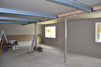
I installed all the battens for the gyp rock ceiling of the outside roof section of the room along with the battens for top and bottom on both sides of the bearers on the section under the house. This was a tedious job as all the screws had to be drilled into 4mm thick steel beams. I also needed to pack out the top of the large ‘C’ section beam that runs the length of the room, along with a packer on the underside. This along with the smaller bearers is done so as the gyp rock sheets can be fixed to them to ‘box’ them in and hide the ugly beams, bolts etc.
I also had the sparky run all the wiring for the room. I have arranged all the power points, with exception to one double point, to be switch on/off by one master switch near the front door. This allows all the layout components to be plugged in and left switched on. Flicking the master switch at the door turns the entire Layout off. Might save leaving the soldering Iron running as well. I have added power points that are also switched at the door for the layout lights. These will be wired to the layout lighting when I get to that stage. I have strategically placed these behind each of the valences on the end walls. I have set these up so as the top level and bottom level can be switched individually depending on what section of the layout I am working on. I have also split the layout lighting down the middle of the room. Left and right, Top and Bottom. Saves having all the lights running when they are not needed. In addition to all these I will have some room lights. Probably fluorescent down lights. Mainly need these while building the layout until the layout lights are installed.
Mate Graham came down to help install all the Gyp rock sheeting. Gee the 6m lengths took some lifting into place. I am having a plasterer make up pre fabricated boxes for the beams. He will also do all the setting and finishing of the walls. So it’s really starting to look like a room now.
January:
The gyp rock man came and set all the walls and ceilings during the Christmas period. Father In-law has been busy slapping on a couple coats of paint and is really looking good. I have been busy fitting the skirting boards around the floors. I will not be fitting architraves around the windows or doors, this way I don’t have to build around them when I construct the bench work, and the windows will be filled in anyway.
On the modelling front for December and January I managed to borrow a fast tracks double slip Jig for some point work in Muswellbrook yard. This is made for Code 70 and has turned out quite nicely. I managed to make from the Jig a single slip and Diamond crossing for the eastern end of Muswellbrook yard, along with a Double slip for the western end (See the track plan below). Although the double slip is not prototypical for the western end it will save a great deal of space and allow for more important features of the yard to be maintained. I may have mentioned in an earlier posting that I am not going to be pedantic about building accurate NSW track work for the lower level but do want reliability and accuracy. I want to be able to see trains running in this lifetime so am happy to use the jigs for the point work. I have a NSWGR jig for all the standard points. I will save all the fine detailed track work for the branch line on the top level.
Between finishing off jobs for people, I have also been working on my Ian Lindsay Models ‘Loaf O Bread’ EHO. Pretty much assembled out of the box with addition of a few extra details. I fitted brass electric markers that I drilled and installed 0.5mm fibre optics. Also added are brake shoes and safety chains on the bogie's. I painted it in the Deep Indian red colours with the thin buff line across the top under the roof cornice. The lining turned out really nice and fine. A little weathering and its starting to look good. Just a few more details to add and it will be ready for service.
I have also destroyed a Powerline MHO. After stripping all the candy paint in Metho, I removed all the horribly over sized handrails with a flat blade knife and drilled holes ready for much finer 0.010” brass ones. The roof section also received some chopping up, removing all the clear window glass from the sides. I filed off the moulded on roof vents and applied my Canvas roof as per my FS/BS car mods and installed roof vent castings. The body was then primed and repainted Deep Indian red. I lined the car with the Tubular lining pen. The thin top line turned out Ok, but thought that the thicker lower line ended up a little thick. Hopefully the weathering will tone it down. I chemically blackened all the pre fabricated handrails and fitted these to the pre drilled holes, aaaaarrrrr much better!
I kept the underfloor but removed all the details from the underside. I did a rough measure up of both the EHO and VHO at the Dorrigo Railway Museum. I fitted a couple of centre beams from styrene U channel along with some cross braces to mount the battery boxes, brake cylinder etc. I also removed the oversized Truss rods and posts. I fabricated correctly tapered brass ones hand filed in the dremel. I soldered on brass rings from a Kieran Ryan S wagon brake detail etch to replicate the big nuts that hold the truss rods to the cross bracing and post. New truss rods and braces are brass wire flattened with a hammer and punch and drilled to accept the posts. I did buy an ILM underfloor detail kit but didn’t end up using it. I used the details from my unwanted Trainorama LHO.......Long story! Also from the LHO I decided to use the Bogie's. This gave me the benefit of utilizing the power pickup for lights. After modifying them so they would roll, I fitted the bogie safety chains then fitted them to the new underframe. Still a fair bit to do yet but looking much better that the standard candy (YUCK) MHO.
February:
The inside of the train room is now finished. I was given some old carpet from a mate just as a temporary measure until I get some of the layout built. I am going to have made a laminex bench top to go along under Muswellbrook yard........At one end of the long wall. I can then move the modelling table from upstairs away from the four year olds hands. Yes, it’s already starting to fill up with stuff! Still more finishing off outside before I can arrange a final inspection from council.
I got in the mood to start a DJH 57 for a mate. I was given a 36 in return. I do a couple hours each night when I get home from work. Seems to help me wind down from work. I have managed to assemble the tender which is now pretty much finished. I am going to fit working markers and a sound chip and will need to prepare holes for the decoder and speaker wire before I can paint it.
I have now started on the chassis. I had machined up a jig for setting out the axles and side rods. It’s basically ‘U’ channel aluminium screwed to a 1” square steel block that has been milled and paste ground perfectly flat and level. The jig ensures all the wheels will touch the track and side rods are correctly spaced. And yes they were out slightly. Elongating the bearing holes ever so slightly allows the axle to be moved to the correct location. Along with the channel is a set of four dummy axles which have a 1mm spigot on each end that the side rods can be attached. I firstly set the rear axles into the chassis soldering the axle bushes to the frame. I then temporarily inserted the other bearings and dummy axles into the frame and sat the frame on top of the channel. With slight downward pressure on the chassis you can check to see if all the axles are rubbing on the channel. I carefully filed out the bearing holes where needed to raise or lower the axle so as the axles rested on the channel. I then started from the back driving wheel attaching the side rods to see if the spigots are centred in the side rods holes. As it turned out, the front two axles needed moving back about 0.015”. After a little more filing I had all the axles perfectly located in the chassis. I was then able to solder the remaining bushes to the chassis.
So in between all the above I still needed to do some work for our AndIan Models projects. We have done a couple more etchings, mainly samples. We have now finalised the etches for our two and three lever lever frames and will soon go into the production stage. These are ever so slightly larger in a couple areas than the originals we had done. Mainly to make them a little less fragile. The two lever frame also works! I can see a slow motion machine being hooked to one…….The mind boggles. The roding chair has also had its problems fixed and will be ready with the frames.


The BLV is also progressing slowly. After a couple bad 3D prototype samples we are now happy with our master. I have fitted all the brass details to one of the bad masters to see where all the bits will go. These will be attached to the master before the casting process saving you guys mountains of work! Again it’s starting to look very good.
Unfortunately no news on the turret tender project. We are still waiting for the brass castings. I hope to have another bulletin when we have the frames ready for sale.
Ok so that’s where I am up to.
Till next time.
Cheers
Ian


