Sunday, September 23, 2012

Three years of digging, finally I struck GOLD!

My research of the Muswellbrook to Merriwa branch started approximately three years ago now and I have in those few years come across many types of research material relating to the line. For me Photographic research is priority for building the layout. I am not all that interested in finding out who was the station master on Friday 5th June 1958 and what train ran through early that day and caught the station master having a pee in the gents! Photographic information is best to capture the accurate prototype of what was what. Most of the line has been well documented in many of the books etc including a fantastic article by Peter Attenborough in Byways of Steam. I have also managed to source material through the Australian Railway Historical Society. Once most of the major holes were filled I try and source items of interest to fill the gaps of what needs to be modelled. Some of these included the station building at Sandy Hollow, The coal loader (serviced by road vehicles) at Muswellbrook and the freezing works at Denman and many more. The railway historical society helped with the coal loader at Muswellbrook along with many other points of interest even some fellow bloggers including Ian Millard helped with the station building at Sandy Hollow along with some fantastic details of Merriwa yard.
The most frustrating to find anything of has been the old freezing works at Denman. There is just a single photo in Byways (number 10 page 72) that shows just the corner of the building and its quality is poor and would realy be of no use for modelling. I begun trying to find material through the Denman Historical Society, Muswellbrook Historical Society, ARHS, NSW state archives, Newcastle Regional Library and the NSW state library, without any luck.
I am always asking people I talk to about the line and if they have or know where I can get info from, one of these is one of our members here in Coffs Harbour, Jim Sowter. Jim comes from Denman and had mentioned a few people I should contact. One of which was a chap that collects farm machinery and general 'old stuff' and was thought to be a bit of a historian. As it turned out he had nothing but I was told to get onto a certain fellow who lives in the old mangers house of the freezing works. When I rang and asked about the freezing works I got the 'I remember the old freezing works' line from the old fella. Lucky I had an hour free! After 15 minutes or so he finally said that he may have some old plans of another Butter factory in Denman that may be of use. He also said that they were somewhere in is roof that was basically full of s#*t! I left it at that and thought that I would never here from him again. Lo and behold several weeks later he rang back, "I found some info on the freezing works for you". " I have eight colour slides of the freezing works, one of every angle around the building". WOW! I literally fell of the chair. GOLD!
He kindly agreed to send me the slides so I could scan them in. He also gave me permission to post them up here and show you all.
The freezing works he tells me opened in the 1930's and was used as a butter factory for many years. It was also used to process wild Rabbits caught by the locals through the great depression. It also produced Lucerne pellets in later years before it was abandoned some time in 1970. The rail siding to the freezing works was removed in 1980 to make way for rebuilding of the line for the Ulan coal project. It was originally thought that the building was of timber weatherboard but the photos tell a different story. Unfortunately a couple were taken out of focus. Note also the cream shed at the rear of the building. This will make a great model on the layout some day. I hope your blown away like I was.


Thanks Garry for the slides. Much appreciated.

Ian
  

Wednesday, June 13, 2012

Fastracks Jig. NSWGR No.6 Code 55

Hi All,
I spoke to Warren from Gwydir Valley Models at the Thornleigh show about seeing if we can have made a Fastracks Jig for a code 55 No.6 with NSWGR cantered sleeper profiles. He thinks that to make it viable he would need to have orders for about 8 of the Jigs. I bought from Warren a No.7 NSWGR jig in code 70 for my mainline and at the time was prepared to hand build all my branch points. This would save a lot of work if a jig was available. I am also going to look into making a detailed frog casting through AndIan models that could be slotted into the points once built. The jigs would be in the NMRA standard profile. So my question is, how many of you would be interested in buying a jig? You could get together with a few friends and share it around. I am unsure at this stage of the pricing but would be similar to the Code 70 jig @ $300. Post a comment if you are interested and I will pass on the interest to Warren. I have two on the list already.

Cheers
Ian

Monday, June 4, 2012

Wrapping up a few things

OK, so as usual I have not posted for a while and the usual excuses......Been to busy, and being a one finger typer, just could not have been bothered. Thought it was about time my finger was given a workout on the keyboard and let you all know what I have been up to. Will try and wrap up a few of the projects I have been working on and fill you in on anything new.


The 57 is now finished. I had a few issues getting the chuff right and also getting a decent sound out of it. At first I used a standard Tsunami K class and a modified soundtraxx cam disk to give the six segments for the chuff. I soon found that the K class sound has a distinctive fourth beat to its chuff sound even when a six lobe cam disk is used. Gerry Hopkins filled me in on his secret for getting the chuff right. Below is a diagram of how a 16 lobe soundtraxx cam disk can be modified and coupled with a Logging Tsunami gets the chuff pretty close to the 3 beat 57. The logging decoder sound doesn't seem to have that prominent fourth beat. I am not all that fussed with the whistle but hey, Better than nothing. I managed to get a very 'short' video while at Brisbane of the 57 running, the camera battery went flat!. It doesn't pull much either witch is strange for such a big engine. I have added a large weight to the boiler witch helps but is still not great. My guess its the nickel plated drivging wheels are too slipery. I am really happy with the weathering as well and will be sorry to see it go to the customer.


Unfortunately I have not really touched the Mike McCormack LFX since the last posting. I have managed to finish off the assembly of the underframe witch prety much complets the assembly of No1. LFX. I have also started on the Bogie's of the second. I had planned on having these for Epping but as you read on you will see other things have taken over and the few issues with the 57 slowed it a little as well. Here is a current shot of the LFX. Pretty much ready for paint. Waiting on the screw couplings and buffer springing components and will need to fit window frames after painting.


As I have mentioned in the last posting, AndIan Models will be attending its first show as a trade stand at the upcoming Epping Model Railway Clubs Thornleigh Exhibition over the June long weekend. We are also helping Alan Tarrant with his exhibition layout. Our small stand will be next to the layout so we can help Alan run trains and man the trade stand as well.
 I have been working on completing one of the BLV's using the body and underframe from the test shot castings. I had this at the Brissy show to show off and was well received. The below shot shows the unpainted and painted sample. It was assembled with no decals and the roof brackets were made with flat brass bar rather than the brass etchings that will come with the kit. I have also left off the turnbuckles as I did not have these at this stage. We now have all the components for 50 wagons that will be available at the show. We have also started the second run as I am sure all 50 will sell at Epping so don't worry if you cant make it to the show. We will take orders after Epping. The price of the BLV's have been set @ $70 each. The brass bogies and wheels makes the kit more expensive than we had hoped but its a really nice model when complete.


I decided to make up a small diorama for the show as well. I made this upo for two reasons, one is so that I could display the AndIan models products, and to act as a nice scene for when I take photos, like the ones above. I made the diorama about 600mm x 400mm approx with a section of handlaid code 55 track down the middle and detailed with the AndIan Models two lever ground frame, roding chairs, compensator's, cranks etc. and one of Gwydir Valleys semaphore signals. All this set around some basic scenery using static grass, much like Bowen Creek. I also decided to try and make both the signal and lever frame work. I ended up getting a 'Bouncer' servo kit form the UK. This makes the signal pause part way through its movement and bounce when at the end of its movement. See video here, and pictures below.


We also received the sample of our water Gin Body that we had 3D printed and only today I got the trial etch for the ladder. I will have this at Epping also. For those of you on the mailing list, keep an eye out for the next bulletin. We are announcing two new projects that will soon be under development.


Lastly, I have now finished off all the small jobs with the house and after a little tidy up is ready for final council inspection, probably after Epping show. This will then mean I can start looking at filling in windows and planning to get started on some bench work. Along with this I am going to need to get back into finishing off getting my much loved Cooper S back on the road. A few months back I had finished rebuilding its Motor and with all that was going on never got around to fitting it back into the car. Looking forward to that.

Hoo roo and see you at Epping.


Ian

Saturday, April 7, 2012

Swap Or Sell

Quick post here. Thought I would give you guys first go at this. I have a Bergs Brass Z26 that I no longer want. I bought this when I first gained interest in NSWGR modelling but as I now have changed my interest to Muswellbrook I no longer need it.(they never ran into Muswellbrook) Thought that it would be better where it can be used.
When I bought it, it was in Mint factory painted condition (I ussume they factory painted these as it was Bloody good) It had never been run. All I have done was added weathering, Brass numbers etc and test run a couple times around a friends layout. Runs perfect. I have the original box as well.
Ultimately I would love to swap it for a Traxx 30T with a bogie tender. Would need to be in similar condition, unpainted would be fine. I am however happy to sell it. $800. I have seen these sell for about this. See pics below.
Email me if you are interested. iphemist@dodo.com.au.


Cheers
Ian

Wednesday, April 4, 2012

LFX Continues

Over the last week I have been working hard on dogbox no.1 spending just a couple hours each night when I get home from work. In the last post I managed to finish off the bogie's, however after posting I was contacted by Mike McCormack about the bogie headstocks. I have been in contact with Mike several times during the construction process and he has been a huge help and great inspiration. Great after sales service. As I had changed my mind about the couplings I will use, I assembled the bogie's with the headstock's suited for the KD boxes with what was supplied in the kit. They dip down in the centre to clear the KD. Mike was kind enough to send me the correct plain headstock's for use with the screw type couplings as per the prototype.  He also included some small delrin sleeves so as the buffers can be sprung, an important addition when using hook draw gear (more on this later). I have yet to swap these over. For those who are considering one or two of these kits, might be an idea to think about this before you order. Mike will supply the kit to suit.
                I then started work on the Body. The body sides are just superb. The scale 2” tongue and groove siding is just beautiful. To achieve the correct appearance for the droplight windows a separate etch for the window frames are provided. The droplight frames are painted before separating from the fret and after they have been fixed in position, there will be a clean, sharp definition between the Venetian/Tuscan Red frames and the Russet window band. They can be modelled in open or closed position as well for extra character. The sides have been machined as matched sets and must not be mixed up. Very minimal clean up is needed.  One of the things that make these kits so good is the several assembly jigs that are supplied with the kit. The use of these makes assembly so easy and so far have found the kit to go together easier than say an AR Kits wagon. The below images show the jig used to align the internal WC walls to the body sides. The jig slips nicely into the WC window, then wall sections can be glued into position either side of the jig.


The completed body showing internal compartments


Take note of the detailed seats and door details. The seat cushions are profiled to the right shape as well. Simply amazing!
Once the body is assembled there are a couple of small details that need to be constructed. One of these is the switch lever on the end of the car. The switch lever and brackets are made from a brass etch and in order to produce a scale 1” square section two separate etches of the lever arms need to be soldered together. This was perhaps the fiddliest of all the construction but care and patience will produce superb results. A spare lever is provided if one stuffs it up. Included is another jig to aid in filing the edges after soldering. I have chemically blackened these ready for installation after the body is painted. The roof is held in place by three brass screws that come up through the closed section of the WC compartment making it easy to access the interior of the car for further detailing after assembly. Also look at the detail of the end roof cornice.


Switch box and lever.


This is the other end of the car with the steps in place. The roof is just sitting in place for the photo and is not yet screwed right down.


Now onto the underframe. Most urethane kits struggle to produce correct step boards and have them cast into the underframe. These kits require the complete assembly of the step boards by using brass castings for the brackets and nickel silver strip for the boards themselves. There is also a small etch for the step treads that are applied after it’s all soldered together. The underfloor is first pinned to yet another Timber Jig that has been machined with a recess down the middle. The step board brackets have a small spigot on the bottom that slot into holes in the sole bar. These holes are drilled out through into the timber jig. Once all the holes are drilled the underframe is removed from the jig revealing all the holes correctly spaced for the step board brackets on the timber. All the brackets are now inserted into the holes in the timber and down onto the step boards. Once they have all been soldered together you simply remove the step board assembly from the timber jig. All the spigot holes will line up perfectly in the underframe. In the next few days I will tackle the rest of the underfloor detail of the underframe.


Cast brass stepboard brackets mounted in the assembly jig. One side has been soldered.


All brackets in place ready for soldering.


Here are the stepboard assemblies ready to be installed to the under frame.
 
Below are the shots of the completed Body. Still need to add the roof vents and WC filler caps.


That's all for now. 
Ian


Monday, March 19, 2012

Moving House!

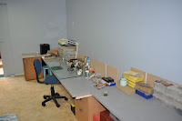
Last Week I decided to pack it all up and move house! It’s the end. But where there is an end there is a new beginning. Yep I have finally moved into my long awaited railway room. I packed up all my modelling table and railway gear and moved it down stairs away from the hands of my 4 year old!
Before I could actually move in I had to erect some new benches for the modelling table. I really wanted a custom laminex bench like a kitchen but when I got the quote back I nearly fell over. It was $900 dollars for a 4.8m x 750mm laminex bench. Just ridiculous. I was hoping to have the bench the same distance out from the wall as the layout bench work under Muswellbrook yard. I could mount a fluoro light behind the lower level fascia to light the bench. While at Bunning’s I found some 2.4m x 600mm laminex bench tops for a hundred bucks. A bargain I recon. OK so they are probably not the quality of proper Laminex but the price was right. The 600mm width proved an issue but was willing to work something out so, I headed home with two.
In order to make sure I have the bench at the right height I proceeded to mark on the wall the roadbed height for each of the two layout levels along with the bench height that will be underneath. I marked these at each of the wall stud locations that I have previously marked on the floor before the gyprock was installed. I soon found a major flaw in my design. With the lower level bench at 1100mm from the floor and my work bench at a normal 750mm, it only left me 300mm to work under when I allow the 50mm for the fascia. I tend to work on the front half of the bench but I think I would hit my head on the fascia. Because I am so greedy and want just about every bit of the wall room as layout it leaves me no other place to put the bench. I came up with a silly idea to mount each of the two benches on sliding drawer runners. Another trip to Bunning’s. This is the result.

If you look carefully you can see the layout height marks on the back wall.

These runners will handle 25kg each and will slide out 450mm. I allowed three for each of the 2.4 bench tops. I also added at the back of the bench a timber wall to stop stuff being accidentally pushed off the back. Once the layout is built I can simply slide out the bench when I need to do some modelling. I can still mount the fluoro in under the lower level bench work behind the fascia to light the work area. When not in use it can be slid under the bench work and covered with layout curtain out of sight. I have also made the bench 150mm off the wall. This brings the front of the bench level with the front of the layout.
I am slowly sorting out all the bits and pieces into small containers and labelled so they are easy located. I still need to make up something for all my small tools so they too are easy accessible.
I also needed a place for all my unbuilt kits, new stuff, Boxes and generally anything I want to hide from the missus, I needed some cupboards. Back to Bunning’s......I’m glad it’s only 5 minutes away. I bought one of their flat pack kitchen cupboard units. 800mm wide, 900 high, 400 deep.  Just a $120. Fits the bill nicely. I will actually end up getting a couple more of these as I progress.
On the modelling front, once the table was set up I got straight back to work. The 57 has come to a screeching Halt. I was able to get it running with the decoder but soon found that the K class decoder has a distinct fourth chuff beat even though I have the 6 lobe cam disk. I emailed Gerry Hopkins who advised to use a logging decoder as it has a three cylinder chuff for shays etc. Just need to wait till it turns up.
Late last year I bought two of Michael McCormack’s LFX Dogbox Kits. I have had a brainwave that I might get in and get these built for the Epping Exhibition in June as I will be helping a mate exhibit his Layout. Probably a long shot but will give it a go. Yep, starting another project before finishing others. I decided to start with the bogie's. It’s quite intimidating when you open the box of one of these kits as there are probably more parts in these kits than in my Mini cooper S! You soon realise what you are paying for. There are many hand crafted and truly mouth wateringly superb urethane and brass castings along with several very fine etches, one of which are for the 2SB Bogie's. The kits also come with very detailed instructions on CD. Every single step of construction is detailed with precise instructions and tips along with a photograph for each step. The instructions alone at first glance can be quite daunting. However as I assembled each of the two bogie's I found that together with these detailed instructions and simply perfect castings and etches they fell together with no problem and actually quite easy, just a little fiddly. After 15 hours here is the result.


I asked Mike at the Sydney show last year if there was anything out of place or incorrect with these kits and he assured me they are close to perfect. I believe him. I still have a few small details to add. I have also built these to suit Hook draw gear. (They can be built for KD Couplers). They are that good they deserve the right couplings!  Going to start on the body next.
If any of you guys want some simply superior hand crafted models forget about the price and get onto Mike and order a couple. You will be amazed at these fine Models. Gee I wonder if I get a commission for the advertising!

I have also been doing a little more for our AndIan models projects. The final etches turned up during the week for 40 or so each of our two and three lever frames. The instructions have been written and we are waiting on the styrene for the concrete platform. We hope to have these ready during April and will have some with me at the Brisbane show if anyone wants some. We still need to do some final work for the compensators etc. They will follow shortly after.
On the bottom of the etch we added the first sample of our four wheel water gin underframe. These tanks were mounted on a 10’ wheelbase steel S wagon underframe. There were a number of variations to these underframes. Of the visible variations, the most obvious is the number of gussets above the spring shackles, which vary from a single T shaped Gusset to two or three simple plate gussets. In addition, some underframes were strengthened by adding a plate under the solebar. The kit will cater for double gusset variety, with the option of building it with or without the strengthening plate. Other variations which are not covered in this kit are the W-irons, some underframe’s having rounded corners, detail differences in brake gear and of course different pattern wheels. The etch at this stage is for just the underframe as we will possibly have these available as a separate item and could be used under another project later on.  A separate etch will be done for the Water gin components. I can honestly say that the sample looks fabulous. It has all the cross members, braces etc. along with all the brake shoe and rigging detail. There are a few small issues but you getting the general idea.


The BLV is pretty much ready to be cast. The new underframe is back from the printers and it too after priming will be ready to cast. Hope to have these for Epping. AndIan Models will have a small stand and will have LWW’s, Lever frames and BLV’s available. Very exciting. I will have another AndIan Models bulletin for those who are on the email list in the coming weeks.

That’s all for now.

Ian