Monday, September 30, 2013

Muswellbrook Roundhouse pt.2 - Rear Wall

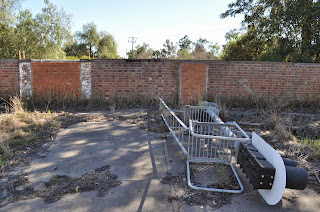
The rear brick wall has five straight double brick sections 5' high that wrap around the back of the roundhouse. The distance determined during the research process revealed that they are 24' long centre to centre. The fifth stall, closest to the road, in the following photo shows that the wall extended out past the corner post by three feet from the centreline of the corner post. You can see the timber stud for the corner of the wall set back this distance. The stud would have attached to the corner post.

 
I did not have evidence of the corner wall of stall no.1, as at present they have removed the wall for easier access to the yard, so I decided to stop the wall flush with the outside face of the side wall. This will need to be extended 6" past the centreline of the corner post (half the distance of the corner post which were 12"x 8" hardwood).  
 
I started by cutting five styrene pieces the required length and height for each of the stalls. I added scale 8" to the height to allow for the concrete floor which I will pour with plaster level with the top of the rail. This was actually done on the prototype as well only the step down was done in the slab before the brick wall was constructed......A bit like a brick veneer house. Next was to laminate two long pieces of styrene to each side of these short pieced. The long lengths were divided up with the correct lengths of each of the stalls so I could scribe and slightly bend the styrene around the back wall. This would give me a gentle bend at each of the angle changes and make the whole thing nice and solid.
 
I lightly glued to the temporary timber base 5 pieced of 20mm square pine on the back side of the rear wall lines previously drawn and set back so the centre of the three styrene pieces (the short ones) was over the centre of the line. Once the glued had dried I could clamp and laminate with MEK each of the three pieces of styrene together.


I wanted to detail the inside of the shed slightly so anything that would stand out needed to be modelled. This included the access doors to the machine shop located behind the rear wall. The rear wall at Muswellbrook has had these access ways bricked in and the different colour bricks used makes them stand out like the proverbials. As can be seen in the lower photo the large double doors can be easily seen from the front of the shed.


Photo Courtesy of Graham Harvey from his Flikr Site.

 
I was able to measure these openings while at Muswellbrook so proceeded to transfer these to the wall section and cut these out down to the top of concrete level. I just so happened to have plastic double doors from an old kit that are a close match to the dimensions. Next was to laminate Slaters English Bond brick sheet to the front and back face of the styrene wall. This was done in long lengths so as to eliminate any unwanted joins.

The piers at the rear of the wall at each of the angle change positions were done by simply adding a second layer of brick sheet over the first. It scales out just about perfectly. Of course at the correct width measured from the prototype. The chamfered top edge was also modelled by gently filing along the outer face at about 45 degrees. At least the rain will run off!  Seen also is the styrene 'slab' for the machine shop. The use of styrene rather than the poured plaster was done as it will most probably be never seen.


To be able to accurately move the completed rear wall section to its new position on the layout, I added some brass pins to the underside of the wall in all the angle change positions and located right in the centre of the wall. Holes drilled in the timber base keeps it all in the correct location. When I move it to the layout I will lay the temporary sheet in the correct location and drill through the holes into the bench work. On the inside lower face I added two 8" x 6" styrene strips glued together. I will use this as 'formwork' for the slab. My idea will be to mask the painted wall and pour the slab level with the top of the styrene and railhead.
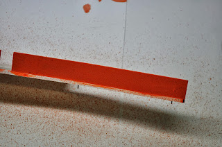
Next was to paint the wall. I have never been real confident at doing brickwork so was time to try a few ideas. I have to admit that the following technique was described to me by Peter Lewis of 'Time and Patients' that we have all admired at the shows. I applied by brush a base colour of Humbrol no.82 matt 'Orange Lining'. This a real orange colour but will tone down with following steps. Next was to add a 'splatter effect' using Humbrol no.100 'Red Brown', no.63 matt 'Sand' and no.33 Matt Black. This is done by slightly thinning the paint with Mineral Turps and using a stiff brush and a gauze or mesh strainer held over the top of the wall, and brushing the bristles on the top side of the gauze. This causes the paint to splatter in fine uneven and random spots over the brickwork. The slight thinning allows the paint to flow slightly and settle on the surface rather than landing and drying in fine spots. Using the paint in the order listed above gives a great effect. Finally, I gave the entire wall a wash of white (with just a small amount of black to turn it grey) Windsor and Newtons water soluble oil paint thinned to a tea like mixture with Isopropyl alcohol to give the appearance of the mortar between the bricks. I ran a cork block slightly soaked in alcohol over the surface just to take off a bit of the white from the face of the brick. I will also use some thinned black to add some grimy rain streaks also. The photos might explain all this dribble better.


The top edge will be painted with Floquil Concrete to finish it all off.

Till next time.


Saturday, September 28, 2013

Muswellbrook Roundhouse pt.1 - research.

As usual, I have delved into yet another project before finishing the previous. There is however a plausible excuse for this....and its the one I'm sticking to!

I have made a start on constructing the roundhouse for Muswellbrook. This is actually the first piece of construction commenced for the layout. So, here is the excuse......I was asked at the last New England convention about doing some etching for the rear wall section of an Anton's roundhouse Kit for a friend and fellow Blogger Adam Homer. A sample section of the rear wall from the kit was sent to me for measurement and inspection. The Anton's kit uses a cast polyurethane frame with clear acetate for the window glass that has lines marked with a black pen to represent the window frames. Apart from the wall section being totally out of square, The window glazing with its black lines just looked terrible!
Originally Andrew and I (AndIan Models) set about to make an etch that was able to be inserted into the Anton's frame, but after much deliberation it was agreed that if we were to spend the time on the etching artwork we may as well make them correct. After all, I was wanting similar etched window frames to the Cowra ones Adam wanted. So, a new wall section needed to be constructed to fit the correct frames.

Fortunately for me, the rear brick wall section still exists at Muswellbrook along with the roundhouse floor and turntable. As Usual, Muswellbrook roundhouse was unique in many forms and I have never been able to get detailed plans of the roundhouse. Over several visits to Muswellbrook I was able to accurately measure the rear brick wall and roundhouse floor. The below three photos show the roundhouse floor and rear brick wall section still standing.


You can see in the lower photo that the stirrups atop the brick wall are still there. These held the base of the main posts that divide each of the window frame sections. There are three sections per stall. Some simple measuring revealed that the distance between the outer posts, or centreline dividing each stall, was 24'. Some time ago Ray Pilgrim 'Bylong Blog' posted a link to some roundhouse drawings along with a link to a flickr site with images of Cowra's Roundhouse. I soon realised that the dimensions matched the drawing. I was also able to scale off the below photo of the rear wall of the roundhouse to determine the height. These dimensions were also compared to those of the Cowra roundhouse.


If you compare photos of the window frames you will see that Muswellbrook's window frames were more rectangular than that of Cowra's Square frames. Although Cowra's square window frames differed by quantity per frame, The distance between the main posts are the same for both. Andrew was now able to draw up some frames from the researched dimensions of both Muswellbrook and of Cowra's two different frames.

Cowra Windows 1
Cowra Windows 2
Muswellbrook Windows

       After waiting patiently for these to be fitted on a test etch, a couple weeks ago I finally received the samples. Before sending the sample off to Adam, I needed to make sure that, A, the etches fit the correct frames, and B, that I was able to construct the frame and reproduce them in polyurethane.
From the drawing and the measurements taken at Muswellbrook I set about constructing the rear wall. Hold Up! Not as easy as that. For me I needed to work out the exact length of the engine shed and its relation, or position, to the mainline. As the drawing did not match the roof profile of Muswellbrook's, I needed to find out if these matched the drawings also. My last trip to Muswellbrook revealed that there were two main posts along the centreline dividing each of the stalls, however they were not evenly spaced like the drawing. The middle post measured 36'feet from the rear brick wall, while the front post was only 28' from the centre post. Looking at the below photo reveals that the front post was set back from the front line of the gutter, or end of the roof rafter which explains the set back distance of the front post. You can also see that I have drawn a line roughly along were the roof rafter and lower truss beam would be and measured the angle with a protractor. 11 Degrees. Pretty close to the drawing. I was told by someone that the roof trusses from Muswellbrook roundhouse were used to rebuild Cowra's???

 
Next was to determine the location of the roundhouse in relation to the mainline. I wanted to make sure I had the shed looking correct when on the layout. I used Google Maps to print out a satellite view of the loco depot area. I drew a horizontal line along the mainline, then using a square, drew a 90 degree line from that, intersecting the centre of the turntable. The filled in pits of the engine shed can bee seen on the image so a line through the centre of stall 1's road was drawn to the centre of the turntable. Again using the protractor I could determine the angle of stall no.1........23 degrees.


As I have not started the layout bench work yet, I used a temporary sheet of MDF to mark out the full size floor plan of the turntable and roundhouse area using the researched dimensions and angles. While at Muswellbrook I measured the distance from the turntable pit wall to the rear of the brick wall of the shed adding on 37'6"(half of the 75' turntable), equalling 170'. The scaled out measurements of the Turntable centre, pit wall, front and mid shed posts and rear wall were marked out on a strip of styrene, holes drilled at these locations and using a small pin through the location of the turntable pit centre, radius line were marked. The five rear wall sections were marked out at 24' centres using the straight line from the turntable centre point. I now have a completely accurate plan of the turntable and shed in its correct orientation. I could now start to construct the shed.


To be continued: