
My holiday's have now come to an end and progress will no doubt slow down a little however I managed to get some more benchwork completed before going back to work.
I was asked in a comment to show a drawing of what the current plan is to be..... (it will no doubt change). Unfortunately I had lost my original drawing file and the 3rd Planit program I did years ago on an old computer. I copied the image file from a really old blog post and done some really quick and crude modifications to that image using 3D paint. The new sections of the mainline are shown in blue, while the branchline(s) is shown in green. This is for the lower level only as at this stage the top may not change. I will use Muswellbrook yard as the datum for explanation and it will be positioned on the Northern wall of my room.

There are two peninsulas within the room. One running east from the west wall and the other running north from the south wall. Both are divided by a floor to ceiling stud wall. The latter is the one I am currently working on. On the original plan the mainline was not going around this section of the layout. The main was to swing around from the east wall and run along the south wall directly into staging. The staging would be hidden below the scenic level.
The new plan is to include an interpretation of St Heliers, the junction for the short branchline to the Muswellbrook no.1 and no.2 Collieries similar to how it was in early 1950. At around 1952 there was a proposal put in place to extend the loop east to Grass Tree, addition of both up and down passing loops and up and down refuge loops. It was also to include the addition of a type O2 signal box. Colour light signals were also to be installed at both the east and west ends of this loop.
This later plan is way to big for the space that I have and I want to stick with semaphore signals only. I do however want to include the signal box. This in mind I decided to change the name of this junction from St Heliers to Heliers Junction. This gives me the ability to model the pre 52 plan with a few additions. I will also wrap the whole passing loop around the above mentioned peninsula rather than try and model it in a big straight line as it was prototypically...…much more interesting. The actual junction will be part way around this S bend. This proved rather difficult and took some carful planning and moving about of the main curves, as it was suggested by my modelling group guys I should maintain a minimum 36" radius on the mainline, a little bigger than originally planed. Between the curved track running from the south wall and the main curve around the peninsula, there is only a small section of straight track to fit the point work for the Junction.
Another issue that arose by having a 42 odd inch peninsula, that was not that big on the original plan, has now encroached on where the west to east peninsula was planned and was to include the helix to the top level. The mainline west out of Muswellbrook intended to run on a small 300mm wide scenicked section of benchwork around the outside of this helix. This would make that peninsula a 50 odd inch radius. I have decided to move this helix to another special room under the house. Access to the helix will be from the west end swinging north out of Muswellbrook yard. I could now bring this other peninsula back to slightly bigger than 36 inches and have a full depth scene rather than 12 inches.
Back to the area I'm working on; The mainline, after it swings around the peninsula, will drop down grade and into staging along the back wall, while the coal branch will climb up and over the top of the staging. The coal loading facilities and associated sidings will be above the staging along the back wall.
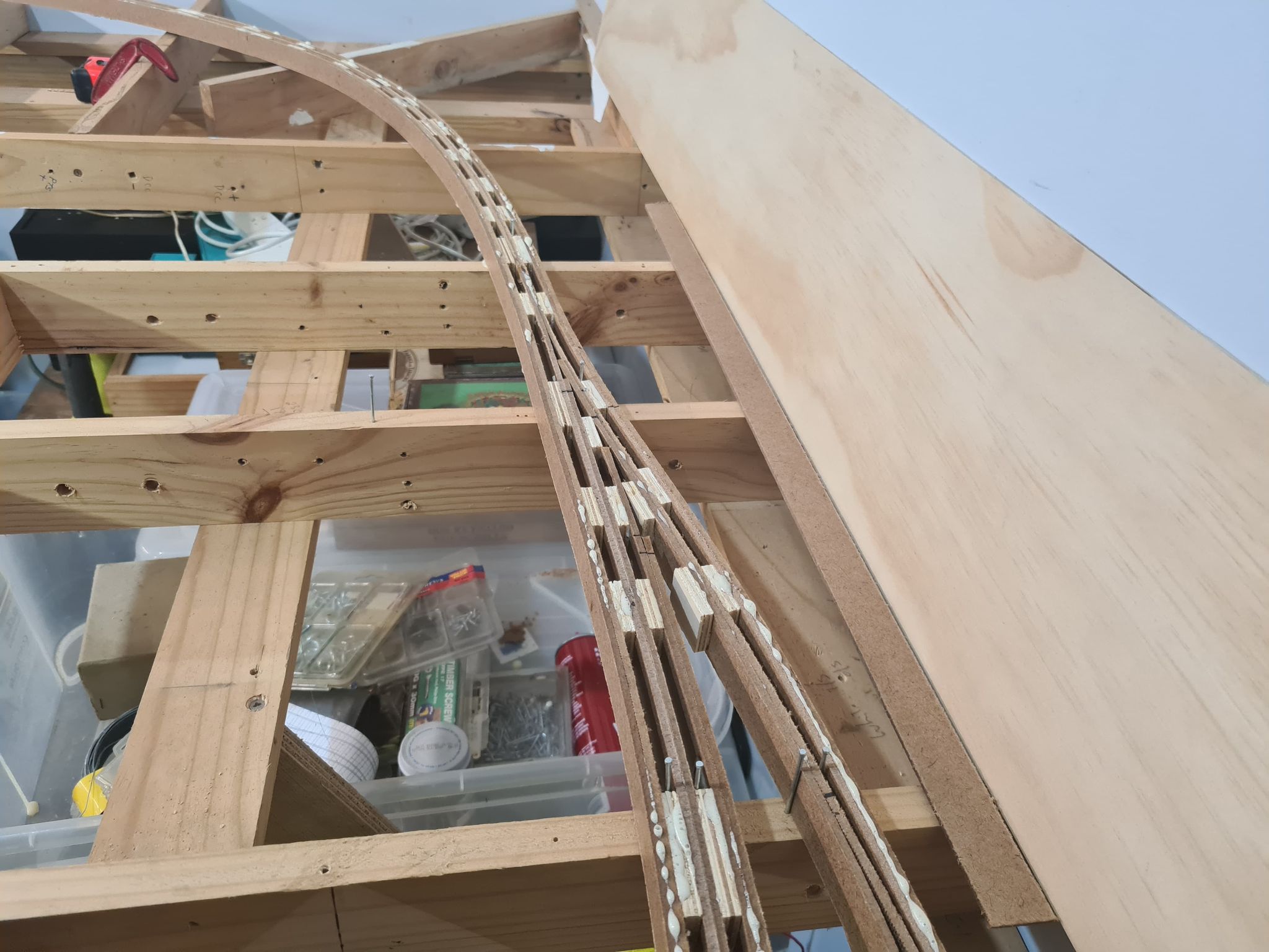
The below images show this new peninsula and the single piece of Masonite roughly laid in place for the mainline. All the benchwork is pretty simple L girder and is all braced back to the bottom of the wall so I have no legs. I have used both dressed Pine and Plywood. Most of this is old crap I have saved from a couple deceased estate layouts I dismantled several years ago. It has a few holes here and there but wont be seen once the scenery base goes down.


Thanks Ian, Appreciate the effort. It gives me something to think about.
ReplyDeletecheers Phil
Great work Ian, keep it up. Looking forward to the next instalment.
ReplyDeletePS: Need to update my Tenterfield blog.
ReplyDeleteCheers Bill W
Good reading
ReplyDelete